Cisco Campus Network Design... on a dime!
You are probably wondering how a Cisco network could ever be built at a low cost. You are right to wonder, because Cisco equipment is quite expensive when compared to other vendors. I would argue that the cost of Cisco equipment is justified by the quality of their products and support, however, that is not the purpose of this post.
In this post I will demonstrate a multilayer campus network design that provides high-availability at the lowest possible cost, with the added benefit of a simple design that is easier to implement than traditional high-availability designs.
This design has many similarities to Cisco's Solution Reference Network Design which is nicely described in two white-papers:
Designing a Campus Network for High Availability
Campus Network Multilayer Architecture and Design Guidelines
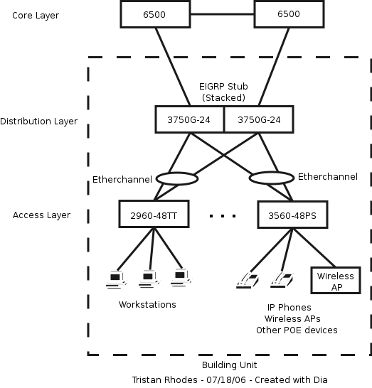
The primary differences between the Cisco design and this one are found in the distribution layer. Take a look at the diagram below, which was created using an open source program called Dia.

The core layer of the network consists of two 6500 Catalyst switches connected by a point-to-point routed link. If you have a small campus, you might be able to get away with cheaper switches in the core, such as the 3750G-12S-E. But if you can afford it, I would highly recommend using the 6500 which is an amazingly powerful and versatile platform. Regardless of which model you choose, the core switches should be running EIGRP as the routing protocol. It would be a good idea for the core switches to be located in different buildings to provide some geographic redundancy.
In my design, the distribution layer consists of two 3750G-24-TS switches that are stacked together. The unique stacking capabilities of the 3750 are what allow this design to provide high-availability at such a low cost. When stacked together, the 3750 switches logically represent a single, redundant switch. Campus buildings should have point-to-point routed links to both of the core routers, with each 3750 handling one of these links.
The stack will be running EIGRP Stub, which is now included in the base software image of all 3750's. I repeat, you don't need to buy the Enhanced Multilayer Image to run EIGRP Stub. Only one of the 3750's will be performing routing, but if that switch fails the other switch will take over the routing process.
The access layer consists of two types of switches. User workstations will be plugged into a 48-port 2960 switch, which provides cheap 100 Mbps connectivity in the access layer. I recommend 48-port switches instead of 24-port switches because of the savings in space, heat, power, uplink ports, and management. Since the per-port cost is very similar, it is a easy decision to choose the 48-port models.
The other type of switch in the access layer is the 3560-48PS. This switch provides 100 Mbps power-over-ethernet (POE) for devices such as IP phones, wireless access points (APs), security cameras, and anything else that needs it. I usually recommend at least one 3560 per switch closet, with the rest of the ports being connected to 2960's. Of course, these numbers can be adjusted to meet your requirements.
If you were paying attention to the diagram, you would see that each access layer switch was connected to both of the distribution switches using etherchannel. Normally, you cannot setup an etherchannel link between multiple devices like this. However, the unique stacking capability of the 3750's makes this possible. Etherchannel is simple to setup, and will provide redundancy and load-balancing of traffic between the two 3750's.
Now that I have described this campus design to you, let's take a look at some failure scenarios to understand how this design provides high-availability:
I hope you have found this design useful, and I would be interested in hearing your thoughts and comments on these ideas.
Update: After writing this article I discovered that it is not possible to enable IP Source Guard on an etherchannel link. If you need the IP Source Guard feature, then do not use etherchannel links between the access and distribution switches. Instead, use the same cable arrangement and let spanning tree block one of the uplinks. You will need to make sure that the distribution layer switch is the spanning tree root for all VLANs by configuring it with a higher priority.
In this post I will demonstrate a multilayer campus network design that provides high-availability at the lowest possible cost, with the added benefit of a simple design that is easier to implement than traditional high-availability designs.
This design has many similarities to Cisco's Solution Reference Network Design which is nicely described in two white-papers:
Designing a Campus Network for High Availability
Campus Network Multilayer Architecture and Design Guidelines
The primary differences between the Cisco design and this one are found in the distribution layer. Take a look at the diagram below, which was created using an open source program called Dia.
The core layer of the network consists of two 6500 Catalyst switches connected by a point-to-point routed link. If you have a small campus, you might be able to get away with cheaper switches in the core, such as the 3750G-12S-E. But if you can afford it, I would highly recommend using the 6500 which is an amazingly powerful and versatile platform. Regardless of which model you choose, the core switches should be running EIGRP as the routing protocol. It would be a good idea for the core switches to be located in different buildings to provide some geographic redundancy.
In my design, the distribution layer consists of two 3750G-24-TS switches that are stacked together. The unique stacking capabilities of the 3750 are what allow this design to provide high-availability at such a low cost. When stacked together, the 3750 switches logically represent a single, redundant switch. Campus buildings should have point-to-point routed links to both of the core routers, with each 3750 handling one of these links.
The stack will be running EIGRP Stub, which is now included in the base software image of all 3750's. I repeat, you don't need to buy the Enhanced Multilayer Image to run EIGRP Stub. Only one of the 3750's will be performing routing, but if that switch fails the other switch will take over the routing process.
The access layer consists of two types of switches. User workstations will be plugged into a 48-port 2960 switch, which provides cheap 100 Mbps connectivity in the access layer. I recommend 48-port switches instead of 24-port switches because of the savings in space, heat, power, uplink ports, and management. Since the per-port cost is very similar, it is a easy decision to choose the 48-port models.
The other type of switch in the access layer is the 3560-48PS. This switch provides 100 Mbps power-over-ethernet (POE) for devices such as IP phones, wireless access points (APs), security cameras, and anything else that needs it. I usually recommend at least one 3560 per switch closet, with the rest of the ports being connected to 2960's. Of course, these numbers can be adjusted to meet your requirements.
If you were paying attention to the diagram, you would see that each access layer switch was connected to both of the distribution switches using etherchannel. Normally, you cannot setup an etherchannel link between multiple devices like this. However, the unique stacking capability of the 3750's makes this possible. Etherchannel is simple to setup, and will provide redundancy and load-balancing of traffic between the two 3750's.
Now that I have described this campus design to you, let's take a look at some failure scenarios to understand how this design provides high-availability:
- In the case of failure of a core router or a link to a core router, EIGRP with equal-cost paths will provide extremely fast convergence.
- In the case of failure of the non-routing distribution switch, the etherchannel between access and distribution layers will provide extremely fast convergence of that link.
- In the case of failure of the active routing distribution switch, the other switch will assume routing responsibilities in 30-60 seconds using RPR+ (Route Processor Redundancy). This convergence time is nothing to brag about, but keep in mind that redundancy was previously not possible at this price.
I hope you have found this design useful, and I would be interested in hearing your thoughts and comments on these ideas.
Update: After writing this article I discovered that it is not possible to enable IP Source Guard on an etherchannel link. If you need the IP Source Guard feature, then do not use etherchannel links between the access and distribution switches. Instead, use the same cable arrangement and let spanning tree block one of the uplinks. You will need to make sure that the distribution layer switch is the spanning tree root for all VLANs by configuring it with a higher priority.

both of your links to the cisco best practices point to the same file.
ReplyDeletethanks for the post
How can you configure more than 6 etherchannels between 2969 and 3750?
ReplyDeleteFor Spanning-Tree root, configure LOWER priority.
ReplyDeleteAlso, with 3750 stacks you might want to use Multiple Spanning Tree (MST), thus:
On 3750 Access Switch:
spanning-tree mode mst
!
spanning-tree mst configuration
name VTP_name
revision 2
instance 1 vlan 100-199, 300-399, 500-599, 700-799, 900-999
instance 2 vlan 2-99, 200-299, 400-499, 600-699, 800-899
!
----------------------------
On Distribution Layer Switch 1:
spanning-tree mst configuration
name VTP_name
revision 2
instance 1 vlan 100-199, 300-399, 500-599, 700-799, 900-999
instance 2 vlan 2-99, 200-299, 400-499, 600-699, 800-899
!
spanning-tree mst 0 priority 4096
spanning-tree mst 1 priority 28672
spanning-tree mst 2 priority 24576
----------------------------
On Distribution Layer Switch 2:
spanning-tree mst configuration
name VTP_name
revision 2
instance 1 vlan 100-199, 300-399, 500-599, 700-799, 900-999
instance 2 vlan 2-99, 200-299, 400-499, 600-699, 800-899
!
spanning-tree mst 0 priority 4096
spanning-tree mst 1 priority 24576
spanning-tree mst 2 priority 28672
If you're an Open Source advocate, then where's the use of OSPF for routing and Linux/BSD based software routers?
ReplyDeleteGreat post, but why not remove the distribution layer in its entirety? Keep the Vlan on the access switch, then both uplinks active with GLBP at the core.
ReplyDeleteCheerZ